 Motor Driver ICs (with MOSFETs) Power Loss Calculation Tool
Before Using This Tool
- This tool is designed to help you calculate the power loss in MOSFETs and the estimated junction temperature in a 3-phase sine-wave PWM system.
- Before using this tool, please read the corresponding data sheet.
- All the device characteristic parameters are typical values at TJ = 125 ℃.
- All the values calculated by this tool are reference values, NOT guaranteed values.
- This tool has NOT been guaranteed to work properly on all browsers.
Runing a Calculation
- In the Product Selection pane, select the product you use from the drop-down list.
- In the Motor Driver Specs pane, move the slider to set a numerical value in each field.
- To run a calculation, click the Calculate button.
− Once you have selected the product, its upper and lower values automatically appear on the Motor Driver Specs pane.
− Selecting a different product from the drop-down list also changes the upper and lower values already displayed.
− Move the slider to enter or adjust a numerical value in each text box.
− To enter a numecial value directly, click or tap (hereafter “click”) in the field.
− When using a keyboard, click to select the slider thumb, and then use arrow keys (left and right) on your keyboard to move the slider.
− You can also enter values exceeding the specified upper values into the Motor Peak Current and Case Temperature fields.
− For details on the modulation index and motor power factor, see “Modulation Index and Motor Power Factor” below.
− To run a new calculation after you made any changes to the values entered, click the Calculate button again.
− If the tool displays an error message or error calculation result after you click the Calculate button, see “Troubleshooting” below.
Reset Button
- Clears all the values entered in the Motor Driver Specs pane.
- Resets all the positions of the slider thumbs in the Motor Driver Specs pane to their default settings.
- Makes no change to the drop-down list in the Product Selection pane.
- Makes no change to the values in the Calculation Results pane.
Troubleshooting
- SYMPTOM: An error message appears when I click the Calculate button.
- SYMPTOM: " NaN " is displayed in the Calculation Results pane.
− No product is selected in the Product Selection pane.
− Any of the user-entered values deviates from the absolute maximum ratings of the product you selected.
Even when the values entered into the Motor Peak Current and Case Temperature fields exceed the setting ranges, the tool displays calculation results after you click OK or Close to acknowledge error messages.
When the values entered into other than the Motor Peak Current and Case Temperature fields exceed the setting ranges, the tool does NOT run a calculation even after you click OK or Close to acknowledge error messages.
− Either one or more fields in the Motor Driver Specs pane are left blank.
− Any of the user-entered values contains numerals or characters other than half-width digits, a half-width period ( . ), or a half-width hyphen ( - ).
− Any of the user-entered values contains a half-width period ( . ) or a half-width hyphen ( - ) at an invalid position.
Examples: “ .3.4 ”, “ .2. ”, “ 0.6. ”, “ 20- ”
Examples: “ .3.4 ”, “ .2. ”, “ 0.6. ”, “ 20- ”
Modulation Index and Motor Power Factor
The following is a conceptual diagram that describes a per-phase control method in a 3-phase sine wave PWM system. The external controller regulates a PWM signal, which is input to your device, by comparing a triangular carrier signal with a sine wave signal. If you need more details on parameters eligible for the Modulation Index and Motor Power Factor fields in the Motor Driver Specs pane, please see the conceptual diagram and equations listed below.
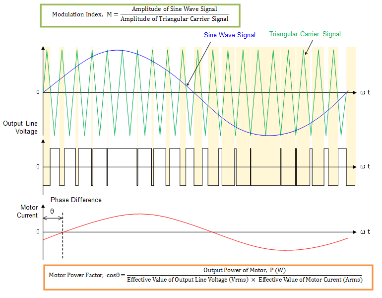
* The motor power factor, cosθ, rises as the motor output power increases, and is expressed as a value ranging from 0.7 to 1.0 at rated output power.
Calculation Conditions
■ Product Selection
■ Motor Driver Specs
* Select the product you use before entering the values for calculations.