C Series
| Input Voltage | AC85 to 264 V |
| Output Power | 300, 450, 650 W |
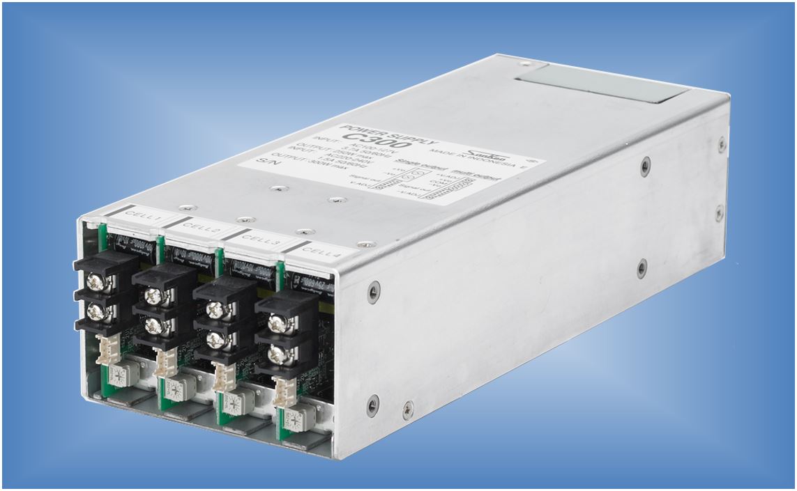
C-Series: Low-Noise Switch Mode Power Supplies With User-Configurable Multiple Outputs
The C-series power supplies save design and production time and cost by allowing end-of-line selection of multiple output voltages to match alternative application circuit requirements, while using the same power supply base unit. DC voltage output modules are slot-mounted inside the base units to provide various combinations of single, dual, or parallel output voltages.
▶ Download 3D CAD Data
▶ Safety Standards and their Marks (PDF)
Features
- You can configure the power supply according to your desired output specifications and power requirements.(Click here for details.)
- Universal input supported
- Three types of power supply systems: 300 W/450 W/650 W
- A wide range of DC cell modules with various output specifications can be selected.
- Quick delivery possible because the switching power supplies and DC cell modules are stocked separately.
- Compliance with safety standards
- Can be used in a variety of fields such as FA control equipment, industrial equipment, and medical diagnostic equipment
- Initial costs such as safety standard certification not required
- Wide range of power management with optional features (Click here for details.)
- Free warranty period: 3 years
Optimum Applications
- General industrial and commercial equipment
- Medical and information equipment
(approved to UL60950-1, C-UL, EN60950 and EN60601-1 3rd )
Model Names
Main units
Model name Legend C***| Series | Output power(***) |
|---|---|
| C | Indicates the total rated output power for 200-V system input (200 to 240 VAC). Example: 650 W |
DC cell modules
Model name Legend C***△○○| Series | Output power(***) | Indicates the output model(△) | Output voltage(○○) |
|---|---|---|---|
| C | 050:50W 130:130W 150:150W |
S: Single output X: Supports parallel operation |
03:3.3V 05:5.0V 12:12.0V 15:15.0V |
Quick Reference
Main units
| Series | C | |||||
|---|---|---|---|---|---|---|
| Model | C300 | C450 | C650 | |||
| Rated input voltage | 85VAC to 264VAC | |||||
| Output power | 250 W/300 W | 400 W/450 W | 600 W/650 W | |||
| Output voltage | Multi-output configuration is possible by combining the DC cell modules appropriately. | |||||
| Dimensions (mm) |
W | 103 | 127 | 127 | ||
| D | 254 | 254 | 279 | |||
| H | 63.5 | 63.5 | 63.5 | |||
| Number of slots | 4 | 5 | 5 One insulating slot included. |
|||
| Optional features | ● | |||||
| Specifications | ● | |||||
| External view | ● | ● | ● | |||
| Technical data | ● | ● | ● | |||
| Operation manual | ● | |||||
| Promotion sheet | ● | |||||
DC cell modules
150 W single output
| Model | C150S03 | C150S05 | C150S12 | C150S15 | C150S24 |
|---|---|---|---|---|---|
| Rated output voltage | +3.3 V | +5 V | +12 V | +15 V | +24 V |
| Rated output current | 26 A | 26 A | 13 A | 10 A | 6.5 A |
| Rated output power | 85.8 W | 130 W | 156 W | 150 W | 156 W |
| Efficiency | 86% (typ.) | 88% (typ.) | 92% (typ.) | 95% (typ.) | 95% (typ.) |
| Output ripple noise | 180 mVp-p | 180 mVp-p | 200 mVp-p | 200 mVp-p | 180 mVp-p |
| Constant voltage accuracy | ±3% | ±5% | |||
| Technical data | ● | ● | ● | ● | ● |
50 W single output
| Model | C050S03 | C050S05 | C050S12 | C050S15 | C050S24 |
|---|---|---|---|---|---|
| Rated output voltage | +3.3 V | +5 V | +12 V | +15 V | +24 V |
| Rated output current | 10 A | 10 A | 5 A | 4 A | 2.5 A |
| Rated output power | 33 W | 50 W | 60 W | 60 W | 60 W |
| Efficiency | 86% (typ.) | 88% (typ.) | 92% (typ.) | 95% (typ.) | 95% (typ.) |
| Output ripple noise | 180 mVp-p | 180 mVp-p | 200 mVp-p | 200 mVp-p | 180 mVp-p |
| Constant voltage accuracy | ±3% | ±5% | |||
| Technical data | ● | ● | ● | ● | ● |
130 W parallel operation output
| Model | C130X24 | C130X36 |
|---|---|---|
| Rated output voltage | +24 V | +36 V |
| Rated output current | 5.5 A | 3.6 A |
| Rated output power | 130 W | 130 W |
| Efficiency | 95% (typ.) | 94% (typ.) |
| Output ripple noise | 250 mVp-p | 400 mVp-p |
| Constant voltage accuracy | ±5% | ±5% |
| Technical data | ● | - |
Safety
Observe the following points.
- *Read the Operation Manual and Detailed Specifications before use.
- *Observe the use conditions, environment, and cautions described in the documents.
Alarm signals
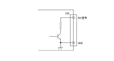
PR signal
This is an alarm signal provided for the main unit. When the input voltage to the main unit falls or the fan stops, the PR terminal becomes open.
LV signal
This is an alarm signal provided for the DC cell module. When the DC cell module output falls or stops, the LV alarm terminal becomes open.
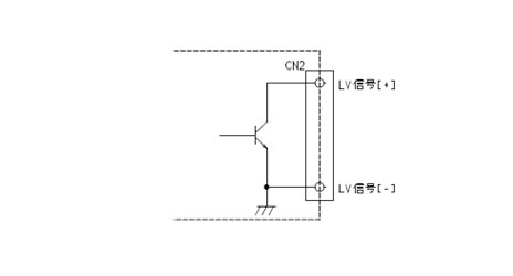
Table 1 Alarm Specifications
| Alarm | Conditions | |
|---|---|---|
| PR | Good | Low (0.8 V or less, 8 mA or less) |
| Bad | Open(35Vmax) | |
| LV | Good | Low (0.8 V or less, 20 mA or less) |
| Bad | Open(35Vmax) | |
Variable output voltage range, remote sensing, and remote ON/OFF control
Variable output voltage range
Each DC cell module has an output voltage adjustment volume knob. When the volume knob is turned clockwise, the output voltage rises. When changing the output voltage, do not exceed the rated output power, regardless of the rated output current. The output voltage variable range depends on the DC cell module. Check the specifications of the DC cell module before changing the output voltage.
Remote sensing
Some DC cell modules support a remote sensing feature. This feature compensates for a voltage drop caused by the output wiring. The compensation voltage value depends on the DC cell module. Determine the compensation voltage from the following table. Before using the remote sensing feature, perform sufficient evaluation and adjustment by referring to the connection example shown below.
Table 2 Remote sensing compensation voltage
| Model | Voltage |
|---|---|
| C150S03, C150S05, C150S12, C150S15 | 0.15 V or less |
| C150S24 | 0.30 V or less |
* Products not listed above do not support the remote sensing feature.
Note the following points when using the remote sensing feature.
- If a contact failure (such as loose screw) occurs in the load line, the load current flows into the remote sensing line, causing heat to be generated. This may damage the power supply. Pay careful attention to the connections.
- For the wiring between the power supply and the load, use a sufficiently thick wire for the output current and set the line drop to a value that is equal to or less than the specific compensation voltage.
- An oscillation waveform may occur in the power supply output voltage or the output voltage variation may become large due to the wiring or load impedance. Be sure to perform sufficient evaluation before use.
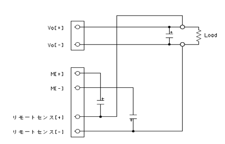
Figure 1 Example of remote sensing connection
Remote ON/OFF Control
The DC cell module has a remote ON/OFF control feature. This feature can turn on
and off the output voltage of any DC cell module according to the signal input to the
corresponding remote ON/OFF terminal.
Output of the corresponding DC cell module is stopped when a voltage of 10 to 27 V is
applied to the remote ON/OFF terminal. Inputting a voltage outside the specifications will
cause a malfunction or damage to the power supply. Be sure to use a voltage that falls within
the specifications. Note that the built-in fan of the main unit does not stop even when the
output of the DC cell module is stopped by using this feature.
The remote ON/OFF control feature is independent for each DC cell module. It cannot be used
to stop the output of all cell modules at once. To stop all the GND common slots at once,
connect the ON/OFF circuits in parallel.
* It is not possible to stop both the GND common slots and insulating slot at the same
time.
The remote ON/OFF auxiliary power supply can be used from AUX (CN1).
Use this for remote ON/OFF circuit operation.
* C650 has AUX1 and AUX2. Use AUX1 for the ON/OFF circuit of the DC cell module connected
to the GND common slots (slots 1 to 4). Use AUX2 for the ON/OFF circuit of the DC cell module
connected to the insulation slot (slot 5). Note that using these in different combinations
other than those above will lead to a power supply malfunction or damage.
Table 3 Remote ON/OFF Control Specifications
| Remote ON/OFF input signal |
DC cell module output status |
|---|---|
| Open or low (0 to 0.5 V) |
Output ON |
| High (10 to 27 V) | Output OFF |
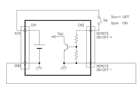
a) Example of using a switch
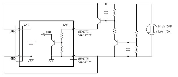
b) Example of using a transistor
Figure 2 Connection example for remote ON/OFF control
Customize
-
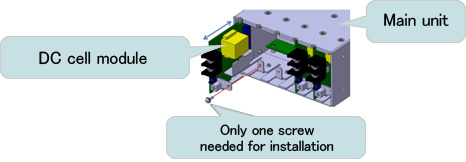
You can configure the power supply according to your desired output specifications and power requirements. Purchase the C series main unit and DC cell modules shown below as required, and use them as a set.
- ・C series main unit: C300, C450, C650
These are AC/DC converters used to supply power to the downstream output.
Select an appropriate unit according to the total power requirement and the number of output slots. - ・DC cell module (output module): C050***, C075***, C130***, C150***
These are DC/DC converters to be connected to the C series main unit. Select a module that has the desired output specifications and connect it to the main unit. The DC cell module can be replaced later according to the application.
- ・C series main unit: C300, C450, C650
Questions or Comments?
Please feel free to contact us if you cannot find the desired product from the lineup.
