 NR263S Calculation Tool
Before Using This Tool
- This tool is designed to help you calculate Peripheral Circuit Constants, Design Values and Power Losses in a NR263S DC/DC Converter system.
- Before using this tool, please read the NR263S data sheet.
- All the device characteristic parameters are typical values at TJ = 25 ℃
- All the values automatically entered into the text boxes in the Calculation Conditions pane are default values (for reference).
- All the values calculated by this tool are reference values, NOT guaranteed values.
- This tool has NOT been guaranteed to work properly on all browsers.
Runing a Calculation
- In the Calculation Conditions pane, move the slider to set a numerical value in each field.
- To run a calculation, click the Calculate button.
Reset Button
- Resets all the values entered in the Calculation Conditions pane.
- Resets all the positions of the slider thumbs in the Calculation Conditions pane to their default settings.
- Makes no change to the values in the Calculation Results pane.
Troubleshooting
- SYMPTOM: " NaN " is displayed in the Calculation Results pane.
Examples: “ .3.4 ”, “ .2. ”, “ 0.6. ”
The Basics Explained
Basic Circuit Connection
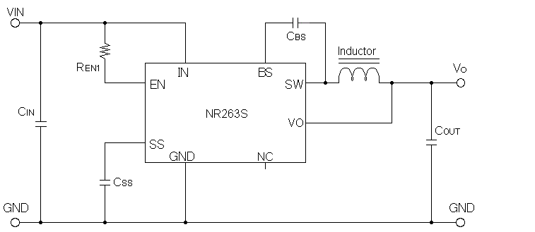
Description of circuit symbols in Basic Circuit Connection
- CIN : Input Smoothing Capacitor
- COUT : Output Smoothing Capacitor
- CSS : Soft-Start Timing Capacitor
- CBS : Power Supply Capacitor for High Side Driver ( Default Value : 0.1µF )
- REN1 : Enable Terminal Setting Resistor ( Default Value : 100kΩ )
- Inductor : Inductance L Value
Inductance L Value Calculation Procedure
- Enter the wished inductor ripple current ⊿IL value into the text box of ⊿IL setting .
- Click the Calculate button and calculate inductance L value.
- Please refer to the inductor manufacturer's catalog and select parts with close values.
- Enter the selected inductance L value into the text box of Inductance L Value Setting.
- Click the Calculate Button and recalculate ⊿IL according to the selected inductance L value.
Setting Criterion of Inductor Ripple Current ⊿IL
| Conditions | ⊿IL | Remarks |
|---|---|---|
| On-Duty<0.5 | 0.2A-1.0A | User Settable Range |
| On-Duty≧0.5 | Below 0.2A | For avoiding Sub-harmonic Oscillation |
Calculation of Pulse-Skip Frequency Fskip
The Pulse-Skip as "Light Load High Efficiency Mode" is a Energy Saving Function installed in the NR263S. It can reduce the number of switching per unit time in the light load condition and reduce power consumption. When the inductance L value is smaller, the Pulse-Skip Frequency Fskip rises higher.
- Entering of load current IO at stand-by load
- Entering of Inductor Peak Current ILP at Pulse-Skip Operation
A value of "Stand-by Load Current IO Setting at Pulse-Skip-Operation" is not maximum load condition when you use. Please use only the stand-by load current value.
The inductor peak current ILP during pulse skipping has dependency on the user-selected inductance L value and the input voltage VIN. The Pulse-Skip Frequency Fskip can be calculated by the equation described in the datasheet, but you must enter the ILP value as an indispensable condition. As for the ILP, please refer to following the reference characteristic chart. Pick up ILP value from the condition of input voltage VIN and the condition of user-selected inductance L value, and enter ILP value into the text box of "Inductor Peak Current ILP Setting in Pulse-Skip-Operation".
VIN vs. ILP reference characteristics by external inductance L value
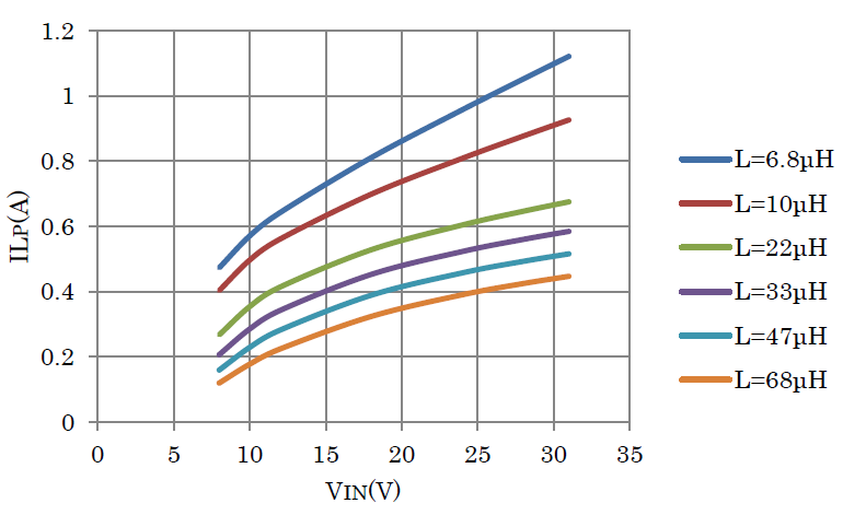
In this tool, the Pulse-Skip Frequency Fskip calculation is only an approximate estimation as the criterion. Please be aware that it is not a guaranteed value.
Supplementary matter
- The entered target efficiency η value is used to estimate the input current Iin approximatly. It is necessary when you estimate the load current of the transformer secondary winding.
- Regarding the setting of the target output ripple voltage, please enter the value how do you want to suppress the output ripple voltage magnitude ? (Unit : mV peak to peak)
- In the calculation result, the ESR requirement value and ripple current of the output smoothing capacitor COUT are calculated by the user selected inductance L value.
- The internal loss of NR263S must be within the thermal derating curve ( Ambient Temperature vs. Power Dissipation characteristic ) shown in the data sheet.