Special Feature: Digital Power supply


Digital Power Management ICs: Built-in MCU (MD6603) Specifications
The MD67xx series, our digital management ICs, incorporate the MD6603 whose functionality is optimized for digital power supplies.
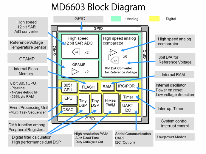
The MD6603 is an 8-bit MCU (Microcontroller Unit) optimal for power control applications including digital power supplies.
In addition to the 8-bit CPU, the MD6603 consists of two 16-bit TnyDSP units?a very unique configuration?and thus brings smart but low-current-consumption control into any power control applications requiring with high-speed arithmetic processing.
What’s more, equipped with extensive analog functions and robust system support functions (e.g., the high-resolution PWM module), the MD6603 will help your power control application achieve higher efficiency and performance.
On This Page:
Built-in MCU MD6603: 4 Key Features
-
Feature 1: Extensive Analog Functions
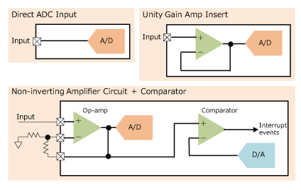
The analog functions built in the MD6603 include fast 12-bit AD converters (4 MSPS; 2 units), comparators with reference voltage generators, and general-purpose operational amplifiers. Programmable interconnection is available among the analog functions, or between the analog functions and external pins.
-
Feature 2: Sophisticated DSP-based Arithmetic Processing by 4 Core Processors Incl. CPU
Besides the main CPU and 2 units of 16-bit TinyDSP, the MD6603 has the EPU (Event Processing Unit) inside. This EPU is an arithmetic unit that can parallelly process 6 threads (channels) with low latency.
So, the MD6603 is capable of parallel processing with these processors: the CPU for system processing, the TinyDSPs for arithmetic processing, and the EPU for complex real-time processing.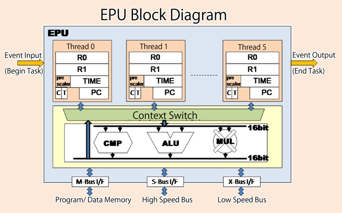
-
Feature 3: High-resolution PWM Function
The MD6603 integrates the PWM module, whose output waveform has a resolution of 1 ns, and can set both duty cycles and cycles.
In addition, the PWM module offers the automatic dead time addition function, and performs a fast response to a duty cycle cut or cycle cut of PWM waveforms synchronized with external events such as a comparator.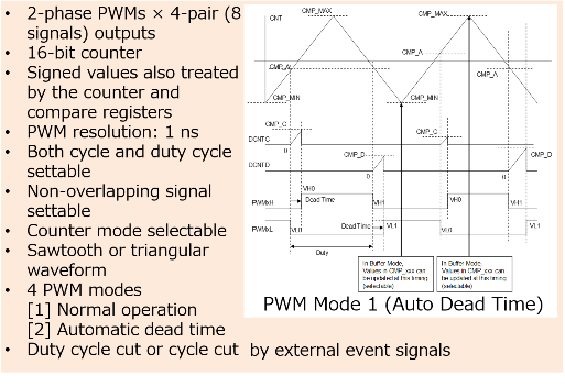
-
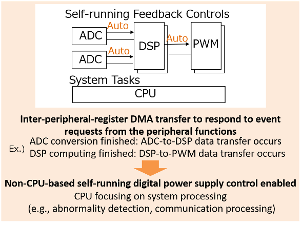
Feature 4: Inter-peripheral-register Automatic Data Transfer (DSAC)
The MD6603 allows automatic data transfer among the registers of the built-in peripheral functions.
For example, when data is automatically transferred among the AD converters, TinyDSPs, and PWM module, the feedback control without the CPU is then enabled. During this feedback control, the CPU can focus on system processing (e.g., abnormality detection, communication processing).
Built-in MCU MD6603: Product Specifications
| Parameter | Specifications | |
|---|---|---|
| Common | Power Supply Voltage, Operation Frequency | Both DVCC (digital) and AVCC (analog) operate with a 3.3 V single power source; 50 MHz (max.) |
| Power Consumption (typ.) | 165 mW in digital; 20 mW in analog | |
| Analog Functions | 12-bit A/D Converter | 2 units; 4 MSPS per unit |
| DA Converter | 8 bits × 6 channels for comparator reference | |
| Analog Comparator | 6 units; fast response | |
| General-purpose Op-amp | 2 units; standalone/unity-gain amplifier (×1 or ×4) | |
| Reference Voltage | 1.2 V output; middle-point GND output | |
| Temperature Sensor | Voltage output; read by the A/D converter | |
| Digital Function | 8-bit 8051 CPU | 8051/8052 compatible instructions; 1 cycle (min.), 3 cycles (avg.) of instruction execution cycle |
| Single-wire Debug I/F | Multiple processing by a single signal: reading from/writing to the internal resources, execution control, breakpoint, writing to the flash memory | |
| Flash Memory | 32 KB; with a cache memory and protection function | |
| Built-in RAM | 1.5 KB (+ RAM directly connected to the CPU × 256 bytes) | |
| TinyDSP | 2 units; enhanced by the saturation instruction and the constant registers, etc. | |
| EPU | 1 unit; 16 bits; 6 threads; 16 input/output events per thread | |
| High-resolution PWM | 2-phase PWMs × 4-pair outputs; 1.04 ns resolution (duty cycle/cycle); duty cycle cut/cycle cut available | |
| DSAC | 16 channels; inter-peripheral-register DMA function | |
| 16-bit Timer | 4 units; 16-bit counter; input/output functions of the pins | |
| SPI,I2C,UART | 1 unit each, external pins independent of each other | |
| GPIO (5 V tolerant for digital) | Digital × 14; analog × 14 | |
| Interrupt Controller | Separate interrupt vectors for each interrupt source; interrupt priority × 2 levels; all the GPIO pins settable as interrupt inputs/td> | |
| WDT | 1 unit; reset/interrupt generation | |
| LVD | Built-in low voltage detection circuit | |
| POR | Built-in power-on reset circuit | |
| IRC | Internal reference clock (12.5 MHz) | |
| PLL | Internal oscillation clock multiplied by 4 (up to 50 MHz) | |
Browse Products List Digital Power Management ICs
Built-in MCU MD6603: Development Environment
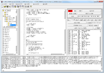
Integrated Development Environment “MD Studio”
Design Support
 Browse Design Support page
We provide “MD Studio,” an integrated development environment for developing CPU programs, for free.
MD Studio supports various functions: editor, C compiler, debugger, and so on.
[Overview]
- Editing source programs, managing projects
- Building C programs and assembly programs (compile/assemble, link)
- Erasing, writing, and protecting the flash memory
- Debug functions (execution): RUN/STOP/STEP executions, setting breakpoints in C source codes
- Debug functions (reference): disassembling, displaying and changing the memories/registers, displaying variables in C source codes
- DSP development environment
- EPU development environment
- Debugger linking
Compact Debug Interfaces “OCD I/F Board”

We offer a debug interface “OCD I/F board” which connects a PC and a target board for program development.
So you don’t need expensive ICE or JTAG debuggers anymore!
Our OCD I/F board only requires a USB to connect your PC, and 3 wires to connect the target board. With these connections, you can debug the programs in the flash memory.
We have also released the circuit diagram of this OCD I/F board.
A New Unique Microcontroller Unit [MD6605]
As a replacement for the MD6603, we have been developing a new unique microcontroller unit, the MD6605, specialized for power electronics control.
This self-developed MD6605 includes the following modules: a 32-bit CPU core, DSPs, EPUs, and a ReRAM which is built on the advanced 22 nm process.
▶Featured Article: MD6605: A New MCU Built on the Advanced 22 nm Process for Sanken's MD67xx Series
Digital Power Management ICs: MD67xx Series Product Page / Inquiry Form
Digital Power Management ICs: Product ListClick Here
Please ask any questions using our inquiry form.


Questions or Comments?
Please feel free to contact us if you cannot find the desired product from the lineup.